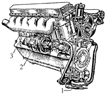
Plate 8 - V-2 Engine
| 1. Water pump |
2. Generator |
3. Engine bearer |

| 1. Water pump |
2. Generator |
3. Engine bearer |
The V-2 engine (Plates 8 and 9) is a four stroke compression ignition engine, water cooled with twelve cylinders at an angle of 60 degrees in two banks. The maximum capacity of the engine is 500 H.P. at 1,800 rpm.
The aluminium alloy crankcase consists of two parts joined together along the line of the crankshaft. On the crankcase top half are cast the cross webs which carry eight main bearings. The main bearings consist of steel shells lined with lead bronze. On the outside of the crankcase top half are fixed the cylinder blocks. Each bank consists of a block of six cylinders integrally cast and a detachable cylinder head. Wet liners are used. The joint between the cylinder head and liners is filled by an aluminium gasket. The lower joint between the jacket and liners is sealed with rubber jointing rings.
Four valves are used per cylinder, two are inlet and two are exhaust (Plate 9). The valves are controlled by the action of the camshaft (#61). Two overhead camshafts are used per blocks supported in seven bearings, and coupled by gears. One shaft is for the inlet valves and one for the exhaust valves. The cams operate directly on mushroom followers secured to the valve stems. At the end of the right hand valve covers (Plate 8) is fitted the tachometer drive which is taken of the inlet camshaft.
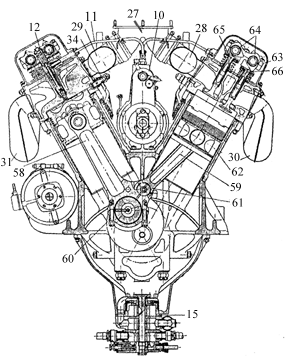
| 10. fuel injection pump 11. High pressure tube to injectors 12. Injectors 15. Oil pump 27. Central tube for inlet manifolds |
28 and 29. Inlet manifolds 3O and 31. Exhaust manifolds 34. Starting valve 58. Master rod |
59. Articulated rod 60. Big end securing pins 61. Wrist pin 62. Piston |
63. Ball bearing of cam shaft 64. Cam shaft 65. Inlet valve 66. Exhaust valve |
The air enters into the cylinders of the engine through the central tube (#27), (Plate 9) which is joined to the inlet manifolds (#28 and #29). The products of the combustion are discharged from the cylinders into the air through the exhaust manifolds (#30 and #31).
The crankshaft has six throws arranged on three planes at angles of 120 degrees. Each throw has two webs of curved shape. The crank pins and main bearings, with the exception of the first main bearing are lubricated by oil through the drilled crankshaft. The end of the crankshaft is splined and onto it is fitted the clutch and fan.
The connecting rods of the V-2 engine, which are mounted on each crank pin are in pairs and consists of the master rod and the articulated rod. The articulated rods are fitted to pistons in the right bank. The master rods are secured to the crankshaft by means of lower detachable caps fixed by pins. The articulated rods are connected to the master rods by means of a wrist pin carried in lugs formed integrally with the back end of the master rod. The lower cap of the master rod is steel lined with lead bronze. In the little ends of both connecting rods bronze bushes arc used for the gudgeon pin bearings. The gudgeon pins are the floating type which are prevented from scoring the cylinder walls by two aluminium caps fixed at each end of the gudgeon pin. The pistons are of forged duraluminium and are provided with five piston rings. The upper four are gas sealing rings and the bottom one is an oil scraper. The piston crown has a special shape to suit the characteristics of the fuel injectors.
The fuel reaches the injector through a thick-walled steel tube (#11) (Plate 9) from the fuel injection pump (#10). In conformity with the load of the engine, the fuel injection pump measures out the correct quantity of fuel and forces it to the injectors under high pressure. The fuel injection pump is situated on the engine between the two banks. The fuel is forced to the fuel injection pump from the tanks by means of a fuel feed pump of the rotary type. Between the fuel feed pump and the fuel injection pump there is a filter, which is situated in the front of the engine between the two banks. This filter cleans the fuel before it enters the fuel injection pump.
The lubrication of the engine is by pressure pump and a dry sump is used. The oil pump (#15) (Plate 9) is attached to the crank case lower half and has three pairs of gears of which one pair functions as a pressure pump, and the other two pairs as scavenge pumps. The oil from the pump reaches the engine through a filter attached to the crankcase lower half.
Cooling water circulates in the jacket of the cylinder blocks under pressure of a centrifugal pump. This water pump 1 (Plate 8) is fastened to the crank-case lower half.
The engine can be started by an electric starter or by compressed air. The electric starter is fitted to the gearbox. An air distributor is attached to the front part of the engine for compressed air starting. From the air distributor compressed air is conveyed trough a steel tube to the starting valves fit too. inside the cylinder head.
The electric generator is carried on a cradle cast into the side of the crankcase top half and is driven by a slipping clutch.
Transmission of the drive to the camshafts and the subsidiary engine assemblies is carried out by means of a bevel positioned on splines at the tail and of the crankshaft. This bevel is in mesh with bevels on the upper and lower vertical shafts. The lower vertical shaft transmits the drive to the shaft of the water and oil pumps and the fuel feed pump. The upper vertical shaft transmits the drive to the air distributor cam, camshaft of the fuel injection pump and at the same time transmits the drive to the inclined shafts which actuate the cam shafts. The electric generator is also driven off the camshaft timing bevel.
The engine rests on a chassis in the tank on four bearers 3, (Plate 8) cast in one piece with the crankcase top half.
The Fuel System
The engine fuels are "Gas Oil" Mark E or diesel
fuel "DT". Plate 10 shows the main fuel feed layout.
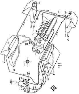
| 1. Fuel feed pump 2. Fuel filter 3. Fuel injection pump 4. High pressure fuel pipe 5. Feed tanks |
6. Front left tank 7. Front right tank 8. Filter caps 9. Drain plugs |
10. Fuel distributor cocks 11. Auxiliary cock 12. Air pump 13. Air distributor valve |
14. Bleeder cock 15. Bleeder tank 16. Pressure gauge 17. Compensation tank |
The system consists of fuel tanks (#5 and #6), fuel feed pump (#1), fuel filter (#2), fuel injection pump (#3), injectors, pipe to fuel injection pump and air cleaner; and besides this the system also consists of cocks, fuel pipes, pressure gauge, compensation tank, small bleeder tank, and an air pressure pump.
Fuel from the front small feed tanks reach the distributor cock (#10) (Plate 10) through a flange welded to the back of the holder of the lower tank.
The fuel fillers of the front tanks are provided with mesh filters and are closed by plugs. On the top of each upper tank a pipe is introduced which passes through the air distributor cock (#13) to the air pressure pump (#12).
To measure the quantity of fuel in the front tanks there is a , dipstick which is pushed through the filler of the upper tank, to do this the mesh filter has to be removed. The dipstick indicates the approximate quantity of fuel in the upper and lower tanks.
The feed tanks are likewise provided with aperture for filling and draining. These apertures are closed by plugs. The feed tanks are connected by a cross pipe in which is fitted an auxiliary cock (#11) (Plate 10). From the back of the right feed tank there is a pipe which leads off horizontally along the right side of thc hull to the fuel cock.
From the top of the right and left feed tanks a pipe leads to the air pressure pump.
When the engine is running, the fuel is taken only from the right feed tank. The fuel flows simultaneously from both feed tanks if the auxiliary cook (#11) is opened. In the event of a defect in the right feed tank it becomes necessary to operate this cock. In this case it is necessary to turn the cock on the union pipe in order to conserve the fuel in the left tank. The full capacity of each feed is 86 litres. The level of the feed tanks can be tested with the same dipstick as for the other tanks using the other side of it.
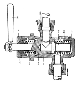
| 1. Body 2. Plug |
5. Nut 6. Hand lever |
7. Mesh filter 8. Spring |
9. Nut |
The fuel distributor cock (Plate 11).
The cock serves the purpose
of turning on or off the flow of fuel from the tanks to the engine. It is
situated on the engine bulkhead at the right. Inside the body of the distributor
cock there is a filter (#7) by means of which the fuel is cleaned before
reaching the fuel feed pump. The body of the cock has four unions, of these
three carry pipes from the fuel tanks and to the fourth is attached the pipe
leading to the fuel feed pump. The handle of the tap has four positions (Plate
10):
The positions right and left are taken facing the front of the vehicle.
From the cock 10 (Plate 10) the fuel flows to the fuel feed pump 1. The fuel feed pump ensures the transmission of fuel under pressure from the tanks through the filter to the fuel injection pump. It is mounted in the crank-case on the fighting compartment side. For lubricating the gland of the fuel feed pump there is a nipple.
The filter 2 (Plate 10) is attached to the front of the engine between the two banks. From the filter a pipe leads off to the pressure gauge. The pressure gauge which measures the pressure of the fuel at the filter is mounted in the instrument panel in the driving compartment.
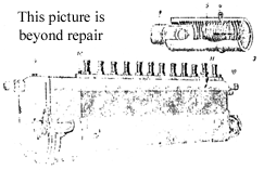
| 1. Fuel priming lever 2. Support of fuel priming lever 3. Rack bar limiter |
4. Rack bar 5. Nut of rack bar limiter 6. Split pin securing nut |
7. Control plug of governor casing 8. Union for filler pipe 9. Lubricator for governor |
10. Air bleeder plug 11. oil measurer 12. Drilling |
Fuel injection (Plate 12)
The pump is designed to measure out a
fixed proportion of fuel corresponding to the load of the engine and to transmit
it under high pressure through the injectors into the cylinders. The fuel
injection pump is situated on the engine between the two banks.
Beginning at 1800-1850 rpm the governor controlling the action of the rack bar 4 of the pump limits the maximum engine revolutions. The maximum number of revs that the governor allows in the advent of a sudden falling off of load does not exceed 2050 per minute. The governor is adjusted so that the engine speed reaches 1800 rpm when working at its maximum capacity. The limiting stop of the stroke of the rack bar and the limiter of the fuel priming lever are sealed. It is categorically forbidden to remove the lead seals and change the setting of the limiters.
Lubrication of the components of the fuel injection pump is carried out by means or an oil filler hole in the top of the body of the pump. The oil level in the body of the pump is measured by a dipstick fitted to the filler hole. The normal oil level is between the upper and lower graduations. The pistons and cylinders of the fuel injection pump are lubricated directly from the fuel itself. The governor is lubricated by oil, filled into a casing through the lubricator (#9) {Plate 12) which is fitted to the upper casing of the governor. Oil should be filled into thc casing of the governor up to the level of the control plug (#7).
The fuel reaches the injectors (#8) (Plate 13) from thc fuel injection pump through a thick-walled steel tube.
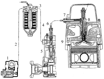
| 1. fuel feed pump 2. Low pressure pipe 3. Fuel filter |
4. Low pressure pump 5. Fuel injection pump type HK-1 6. High pressure pipe |
7. Injector union 8. Injector 9. Combustion chamber |
Air Pressure Pump
Before starting the engine it is necessary to
have the filter and all pipes leading from the tanks to the fuel injection pump
primed with fuel. This entails the transmission of fuel from the tanks to the
fuel feed pump. The pressure necessary to do this is 0.2-0.3 atmospheres. The
hand operated air pressure pump (Plate 14) which is fitted in the front or the
vehicle is used to supply this necessary pressure in the tanks. From this pump
(#12) (Plate 10) a pipe leads to thc air cock (#13).
Air distributor cock The cock is fitted on the left of the driver. Its purpose is to link the appropriate fuel tank to the air pressure pump in order to put it under pressure for starting purposes and also to connect the tanks to the atmosphere during the time the engine is running.
The cock has five unions. To one union, the lower one, is connected the pipe from the air pressure pump, to three unions are connected pipes from the fuel tanks and one is connected to the bleeder tap
By turning the handle of the cock, one or the other of the fuel tanks can be connected to the air pressure pump, the remaining tanks are joined to the atmosphere through the opening in the body of the cock. When the position of the handle is against "MA" all the tanks are connected to the atmosphere and the air pressure pump to the air outlet cock. The other positions of the handle are marked thus:
For bleeding the air from the fuel filter and the fuel injection pump there is a small tap on the instrument panel (#14) (Plate 10). Air can reach the fuel filter and fuel pump either when stationary owing to there being no fuel in the pipes or when moving through the pipes being air locked when the tanks are low.
The bleeder tap consistes of a three-way cock with three unions. The unions connect pipes leading from the fuel filter, air pressure pump and the small bleeder tank.
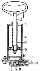
| 1. Hand lever 2. Rod 3. Upper cap |
4. Body 5. Spring 6. Piston |
7. Lower body 8. Ball 9. Valve spring |
10. Adaptor 11. Pipe |
To expel air from the fuel filter before starting it is necessary to build up a pressure of 0.2- 0.3 Kg/cm2 in the tank which is switched on by the distributor cook and to turn the bleeder tap to the position marked "CIIYCK BO3AYXA"(Air out). (See plate 10 and the plate on the instrument panel). Under force of the pressure created in the tank, air, and afterwards fuel, goes from the fuel filter through a small tube, passing the pressure gauge, to the bleeder cock and through this to the bleeder tank. Air first goes through into the bleeder tank, then fuel and air and finally, only pure fuel. In order to eliminate air bubbles it is necessary for the handle of the tap to be in the working position (pointing downwards). If all the air has not been successfully removed from the fuel injection pump by means of the bleeder tap then it is necessary to open the engine hatch and withdraw the plug 10 (Plate 12). After releasing the air from the pump the plug should be replaced.
The position !IIPOAYBKA' (inflate) of the bleeder tap should only be used if the fuel oil congeals in the pipe leading to the pressure gauge. To blow out this pipe it is necessary to disconnect it from the fuel filter, set the handle of the bleeder tap to "IIPOAYBKA" and the air cock to "MA" and blow the pipe out by means of the air pump. The small bleeder tank is painted yellow and is positioned in the nose of the hull behind the instrument panel.
Fuel injection pump controls The fuel injection pump controls regulate the quantity of fuel entering the cylinders. The lay-out of the control system is seen in (Plate 15)
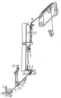
| 1. Foot pedal 2. tie-rod 3. Lever on the lower bracket 4. Lever 5. Lower vertical tie-rod |
6. Upper lever 7. Upper vertical shaft 8. Lover 9. Tie-rod |
10. Forked lever 11. Spring 12. Hand lever 13. Fork |
14. Support for rod 15. Rod 16. Supporting bolt 17. Vertical spring |
On depressing the pedal (#1) the fuel priming lever on the fuel injection pump is operated by means of a system of tie rods and levers.
On releasing the pedal the spring (#11) returns the control to its original. position provided that the hand lever (#12) does not limit the movement of the tie-rod (#2). The hand lever (#12) is set to a minimum number of engine revs so that on releasing the pedal the engine will not fade.
Adjusting the fuel injection pump controls
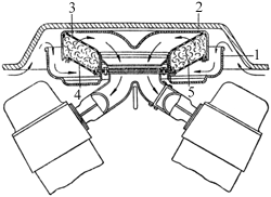
| 1. Air Cleaner. 2. Lower vessel |
3. Upper detachable cover. 4. Upper mesh |
5. Lower mesh 6. Wire wool. |
Air Cleaner (Plate 16)
The air cleaner serves to purify the air
from dust before it enters the cylinders. The air cleaner is supported on
brackets welded to the inlet manifold. Thc basic filter element is oiled wire
wool. Tanks of the latest modal (with V-2 engine) also have in the transmission
compartment two "Cyclone" air cleaners.
Action of the engine feed system
When the engine is running the
fuel feed pump of the rotary type 1 (Plate 13) supplies fuel from the tank to
the fuel filter 3 under a pressure of 0.5 -0.7 Kg/cm2. The filtered fuel goes on
to the fuel injection pump 5. In conformity with the firing order and the load
of the engine, the fuel injection pump forces at high pressure the necessary
quantity of fuel into the injectors. Maintenance of the engine fuel system. The
main defects of the fuel feed system are due to obstructions in the fuel pipes
owing to bad engine maintainece. The following points must be watched :
If any defects occur in the fuel injector pump, the fuel feed pump and the fuel injector pump should be detached and handed over to a base workshop or to a special fitter.
The air cleaner should be periodically cleaned. The period depends on the terrain and time of the year. In summer when the atmosphere is dust laden, the air cleaners should be cleaned and oiled after 10 hours of engine running. In the winter only after 20-25 engine running hours. The air cleaners should be cleaned with kerosine.
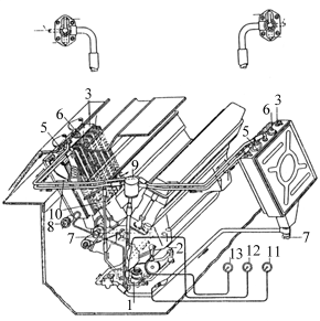
| 1. Oil pump 2. Oil radiator tank 5. Change-over cocks |
6. Filler plug 7. Threaded grease guns for lubricating the spindle of the water pump 8. Compensating tank |
9. Junction pipe 10. Fresh oil thermometer |
11. Used oil thermometer 12. Pressure gauge |
The lubrication system (Plate 17) consists of two oil radiator tanks 3, oil pump 1, oil filter 2, pressure gauge 13, two thermometers 11 and 12, and a compensating tank 9. In the latest models, oil tanks are not in the form of radiators (i.e. without cooling fins), and the change-over cock is not fitted.
Construction of Lubrication System The oil radiator tanks These are situated in the engine compartment at the sides. Their inner surfaces (facing the engine) are fitted with laminated fins (or radiator sections) where possible. The full capacity of each tank is 57 litres. The minimum possible quantity of oil is 10 -15 litres. A dipstick is provided and is inserted in the filler plug in the oil tank. In the bottom part of the tank there is an oil filter. At the base of the filter there is a threaded drain plug 7. To remove the oil from the tank this plug should be unscrewed two or three turns - it is not necessary to unscrew it completely - and the oil will flow from the opening. The inside of the plug is adapted to take a hose for draining the oil into a vessel. The filler has a mesh filter. The top of the tank has a change-over cock the handle of which has three positions:
1. Forwards (towards the front of the vehicle) - oil can be forced directly by the pump through the cock into the tank. 2. Backwards - radiator on. The oil is cooled to air temperature as it flows through the radiator fins and it passes into the oil tank to be taken up again into the engine. 3. To the side - the tank and radiator are shut off.
When the engine is running the handles of the change-over cocks 5 (Plate 17) of both tanks (those which have radiators) must either be in the position "HA BAKN" (to tank) or "HA PADNATOR" (to radiator), it is forbidden to leave the handle pointing to the side.
The junction tube 10 serves to connect both tanks to the crankcase and also to drain off oil and foam when the tanks are overfull.
The oil pump which is fixed to the crankcase bottom half serves to force oil under pressure to the engine and to scavenge the used oil.
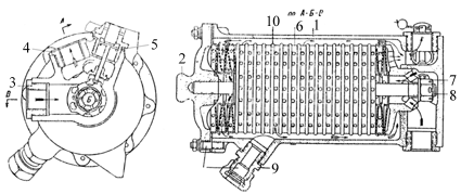
| 1. Body 2. Cap 3. Adaptor for inlet pipe |
4. Adaptor for outlet pipe 5. Union for safety valve 6. Filter disc with rim outside |
7. Nut 8. Central stud |
9. Union 10. Filter disc with rim inside. |
The oil filter (Plate 18) is attached to the front of the crankcase bottom half.
Action of the lubrication system In certain exigencies it is possible to fill not more than 5-6 litres of oil
directly into the crankcase through the breather. The spindle of the water pump
should be lubricated periodically by thc threaded grease gun (#3) (Plate 17).
Each radiator consists of two collector tanks at the top and bottom connected
to each other by copper tubes. To increase the cooling surface of these tubes,
they are covered with thin copper laminations.
The lower collector tank of the radiators are joined by pipes to the water
pump.
The top collector tank of the radiator has two pipe connections, one to the
jacket, the other to the T-piece for draining water from the radiator. In the
middle of this collector tank there is a union to which is joined to a
thermometer. The top right collector tank has, in addition to these pipe
connections, yet another pipe for leading off steam to the steam valve and an
inspection plug for testing the level of the water.
The centrifugal fan is mounted on the flywheel and servee to blow air round
the water and oil radiators.
The air valve with T-piece filler (#1) (Plate 21) is connected to both
radiators and is designed for filling up with water. In the cover of the T-piece
an air valve is fitted adjusted to operate at pressures of 0.08- 0.13 Kg/cm2
lower than atmosphere. Thus it is impossible for a pressure lower than
atmosphere to form inside the radiator as a result of the rapid cooling of the
system when the engine is stopped.
The steam valve (Plate 22) is fitted to the upper half of the engine
Compartment bulkhead. The body of the valve is connected to the steam escape
pipe of the right radiator. The steam outlet pipe (#11) of the valve leads
outside through a hole in the hull of the tank.
The nut (#1) of the valve serves as a control and is situated inside the
fighting compartment.
The steam valve is adjusted to open at pressures of 0.6-0.8 atmospheres above
atmospheric pressure, thereby safe-guarding the radiators from internal
pressure.
When filling up and draining off water, it in necessary to turn the nut (#1)
to the right or left so that the cooling system is connected to the atmosphere.
When filling up or draining off is finished. the steam valve must be closed
again by screwing up the nut.
Starting up the engine by compressed air The compressed air system is an
alternative method of starting the engine and is used when the electric starter
will not work.
The compressed air bottles are fitted on special brackets (#2) in the nose of
the tank.
The capacity of each bottle is 10 litres and the maximum pressure in the
bottle is 150 atmospheres. Each bottle has a valve by means of which it is
connected to the control system. Air from the bottles travels through the pipe
(#4) to the T-piece (#5) and to the reduction valve.
The T-piece is designed for refilling the bottles with air without removing
them from the vehicle.
The reduction valve (#8) is designed for adjusting the air pressure at the
air distributor of the engine. It is mounted at the left of the driver.
The pressure gauge which reads up to 250 atmospheres indicates the pressure
in the bottles (when the valves are opened). Procedure for starting the engine
by compressed air is described in Chapter VII - Maintenance.
Care of the Compressed Air Starting System The pressures in the bottles must not be lower than 40 atmospheres in the
summer and not lower than 60 atmospheres in the winter. The pressures should be
increased in the case of a worn engine. If the pressure is lower than
instructed, starting will be made more difficult.
Both pairs of scavenge gears in
the oil pump force oil into the compensation tank (#9) (Plate 17) whence it
flows through the change-over cock (#5) into the tank-radiators. The
compensation tank serves to return the used oil equally to both tanks. The
pressure of the oil system which is indicated in the pressure gauge must be 6-9
Kg/cm2. This oil pressure is obtained by the help of the relief valve
situated underneath the top or the oil pump. The temperature of the oil entering
the engine (thermometer #11) must be more than 40oC and must not
exceed 80oC The temperature of the oil leaving the engine
(thermometer #12) must not exceed 100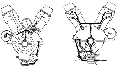
Plate
19 - Plan of Engine Lubrication
N.B. In V-2 -S4 (Series H) engines, the
lubrication is conducted from the front.
ENGINE COOLING SYSTEM
The engine cooling system (Plate 20) is comprised of the water jacket of the
cylinder blocks, water radiator (#1), water pump (#2) with cock (#3),
centrifugal fan (#14), T-piece (#8) with air valve, steam valve (#12) and pipes.
The capacity of the cooling system is 90-95 litres.
Construction of the Cooling System
Radiators
Two tubular type radiators are installed in the vehicle
inclined at each side of the engine.
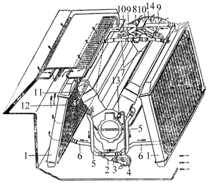
Plate
20 - Engine Cooling System
1. Water radiators
2. Water pump
3. Drain cock
4. Drain
pipe 5. Pipes
6. Pipes supplying the pump
7. Hose connection
("durite") for filter
8. Filler T-piece 9. Pipes taking water from engine
10. Pipes taking steam from the
cylinder heads
11. Pipe for taking off steam from the radiators12. Steam valve
13. Lead to drain cock
14. Centrifugal
fan.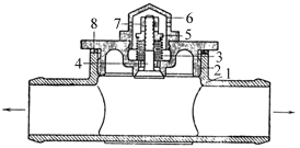
Plate
21 - Filler T-piece with air valve
1. T-piece
2. Body of air valve 3. Spring
4. Valve5. Nut
6. Cap 7. Split pin
8. Packing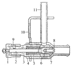
Plate
22 - Steam Valve
1. Nut
2. Valve spindle
3. Adjusting nut4. Chock nut
5. Spring
6. Body of valve7. Rubber valve
8. and 9. Screws10. Bracket
11. Steam escape pipeCONSTRUCTION AND ACTION OF COMPRESSED AIR STARTING SYSTEM
The system of starting the engine by compressed air (Plate 23) consists of two
compressed air bottles, a reduction valve (#8), pressure gauge (#9), air
distributor to cylinders (#12) (mounted on the engine), pipes (#13) from the air
distributor to cylinders and twelve outlet valves (one for each cylinder).
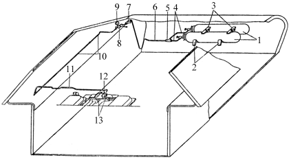
Plate
23 - Layout of Compressed Air Starting System
1. Compressed air bottles
2. Brackets
3. Clamps
4.
Pipes5. T-piece
6. Pipe Connecting T-piece
7. T-piece for filling
air bottles 8. Reduction valve
9. Pressure gauge
10. Pipe11. Transverse pipe
12. Air distributor
13. Pipes connecting
air distributor to cylinders.
It is necessary to test
the air pressure in the bottles periodically during inspection of the vehicle.
INSTRUMENT PANEL
The instrument panel carries the following instruments :