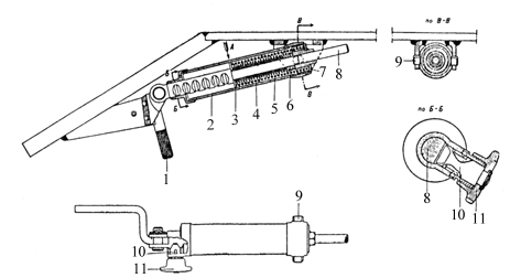
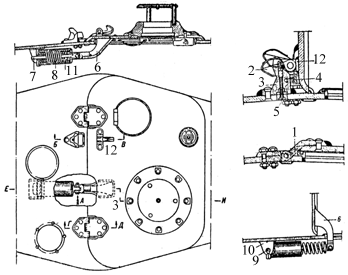
Plate 1 - Balancing mechanism of the driver's hatch
| 1. Hand lever 2. Body 3. Plate |
4. Spring 5. Centralising bush 6. Spring |
7. Rear flange 8. Rod 9. Pivot |
10. Lock 11. Handwheel |
The driving compartment is situated in the front part of the tank; it contains the seats of the mechanic-driver and gunner-wireless operator, the driving controls, instruments, engine controls and electrical equipment, machine gun, part of the fighting equipment. wireless set (not in all tanks) , three periscopes, control for rear louvres, two compressed air bottles, spare parts, tools and ancillaries.
The driver's hatch is in the glacis plate. In the floor at the feet of the gunner-wireless operator, there is an auxiliary escape hatch which is closed by an armoured door from within. The driver's hatch is fixed with hinges and has two locks which can be opened from within by pulling a strap which connects both locks. To assist opening the hatch a balancing mechanism (Plate I) is provided together with a catch and handwheel for supporting it in the open position.

| 1. Hand lever 2. Body 3. Plate |
4. Spring 5. Centralising bush 6. Spring |
7. Rear flange 8. Rod 9. Pivot |
10. Lock 11. Handwheel |
The fighting compartment is situated in the middle part of the tank. It
contains the seats of' the tank commander and the turret gunner. The turret
which rests on a ball race on top of the fighting compartment contains the 76
mm. tank gun and the ![]() machine gun co-axially mounted,
part of the fighting compartment and observation instruments.
machine gun co-axially mounted,
part of the fighting compartment and observation instruments.
Behind the removable plate of the partition are four fuel tanks - two at each side. In the middle and at the sides, part ,of the fighting equipment is kept. In the right hand corner there is an electric fan. On the roof of the fighting Compartment there arc six openings -three at each side. The central openings are used for filling up the tanks with fuel; and the remainder are for inspection, maintenance and lubrication of the suspension. In the floor of the fighting compartment there are three openings under the fuel tanks for draining off fuel ( the openings are closed by threaded plugs). There are also four slits for the removal and inspection of the suspension units. These are closed by caps on the outside of the tank.
The Engine compartment is situated behind the fighting compartment and is separated from it by a dividing bulkhead (Plate 2). The following are installed in the engine compartment: the engine, two water cooling radiators, two oil tank , radiators, four accumulators. The floor of the engine compartment is fitted with an access door for the oil pump and water pump ( this is closed by an armoured cover on the outside of the vehicle), an aperture for draining water and three slits for the removal and inspection of the suspension (these slits are closed by means of armoured covers on the exterior of the vehicle).
The engine compartment roof has a large hatch for access to the engine (this is closed by a cover and secured by a lock), two air louvers over the radiators. There are four access plates at each side; the central ones provide access to the filler plugs and oil tank cocks and the ones at each side are for access to the adjustment of the suspension.
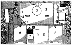
| 1. Hand lever for louvre control 2. Cover of the ventilating hatch 3. Upper central removeable plate |
4. Threaded grease gun 5. Access door for fuse box 6. Access door for oil cock |
7. Fuel distributor cock 8. Lower central removeable plate 9. Nut of steem valve |
The transmission compartment is situated in the rear part of the tank; it contains the engine clutch with centrifugal ran, gearbox, steering clutches with brakes, electric starter, final drives with two fuel tanks. The floor of the transmission compartment is provided with two apertures at the side for draining fuel (these apertures are closed by threaded plugs on the outside) and one opening Jon thc middle under the gear box for draining off oil (this opening is closed by means of an armoured cover from the outside).
In the roof of the transmission compartment, over the fan there are air inlet louvres (Plate 3). These are provided with a metal netting for keeping out foreign bodies. These are two access plates in the roof for the fuel tanks and filler plugs.
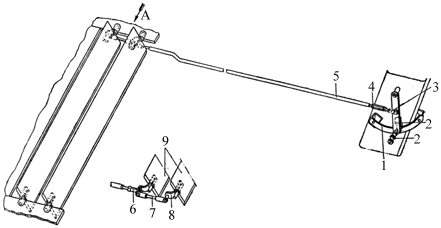
| 1. Segment 2. Hand lever with lock 3. Eye |
4. Lost motion device 5. Tie-rod 6. Eye |
7. Tie-rod 8. Lever 9. Louvres |
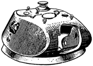
The rear plate of the turret is removable. Fixed to the sides of the turret
are the observation instruments and underneath them a revolver port is provided
which is closed by means of a conical plug. This plug is inserted from the
outside and pushed open by a steel lever. The rear part of the turret roof is
fitted with an access hatch on the top of which there is a signal port. Fitted
on to the front part of the roof are the instruments ![]() -5 and
-5 and ![]() -7 and between them a hatch is
provided for ventilation which is covered by an armoured cap. The turret is
prevented from coming off by turret clips. In the rear clip is incorporated a
travelling lock for the turret.
-7 and between them a hatch is
provided for ventilation which is covered by an armoured cap. The turret is
prevented from coming off by turret clips. In the rear clip is incorporated a
travelling lock for the turret.
| 1. Hinge 2. Pawl 3. Bracket |
4. Rubber pad 5. Knob 6. Bracket |
7. Lock 8. Spring 9. Pivot |
10. Bracket 11. Casing 12. Hinge |
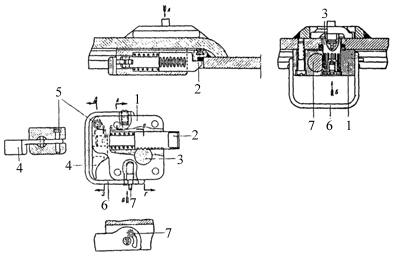
| 1. Body 2. Supporting shaft |
3. Vertical shaft 4. Lever |
5. Stud 6. Hand lever |
7. Lock |
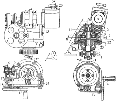
| 1. Pinion 2. Cone friction clutch 3. Shaft 4. Planet carrier 5. Lower casing 6. Upper casing 7. Worm wheel for the hand wheel |
8. Satellite wheels 9. Satellite pins 10. Pinion 11. Worm wheel for electric motor 12. Worm 13. Worm for handwheel |
14. Handwheel 15. Electric motor 16. Driving pinion 17. Parasite pinion 18. Driven pinion 19. Rubber ring |
20. Electric motor handwheel stop knob 21. Nut retaining the bodies 22. Packing disc for the lower casing 23. Disc with worm wheel 24. Cover 25. Electric motor control handwheel |
To turn the turret by hand it is necessary to rotate the handwheel (# 14), in the direction required. To use the electric motor it is necessary to press knob (# 20) of the catch and turn the handwheel in the direction required. When the handwheel is in the neutral position, the catch returns automatically. The clutch spring of the gear (# 1), when in the fully compressed position, should measure 32-35.5 mm. long.
Stowage of MG Magazines.
In a fighting tank modified for wireless set, 62 magazines are stowed :
In a tank with wireless set (Commander's tank), 46 magazines are stowed :
| Back to the Main Page | Disclaimer |